Introduction
Vapour belt exchangers are not all that common (at least compared to more typical exchanger), so it is not unreasonable that many folks do not understand specific mechanical integrity considerations for the slotted regions. They are not “just internals”.
Through a few recent discussions related to vapour belt style exchangers, it was evident that both inspection and engineering personnel didn’t necessarily understand the design considerations for this type of equipment.
The importance of the slotted region in the shell was not well understood. This article is intended to outline some of the basic background for mechanical integrity (MI) personnel to consider when looking at in-service vapour belt exchangers, especially if there is significant corrosion in the slotted region.
What is a Vapour Belt Exchanger?
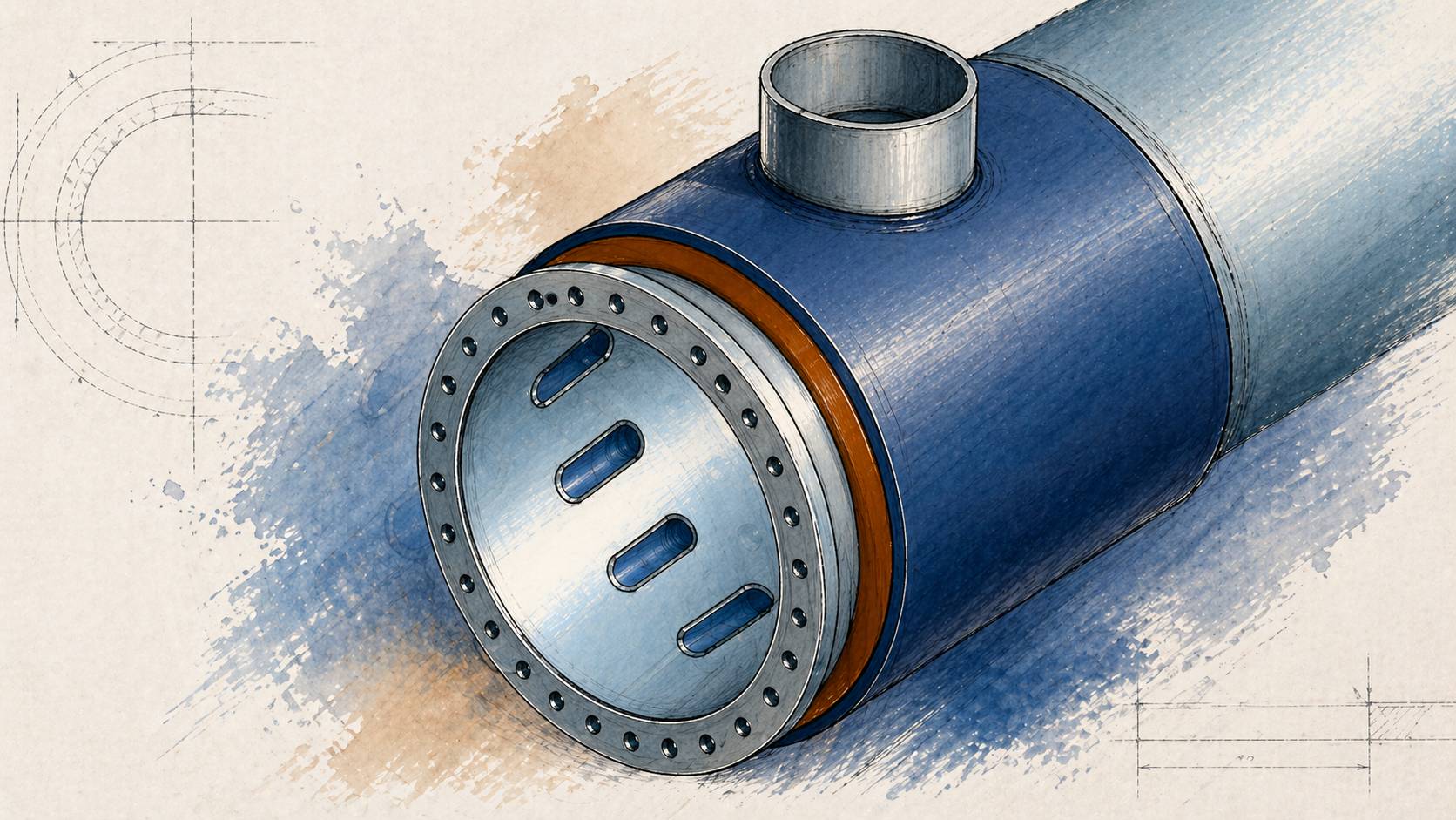
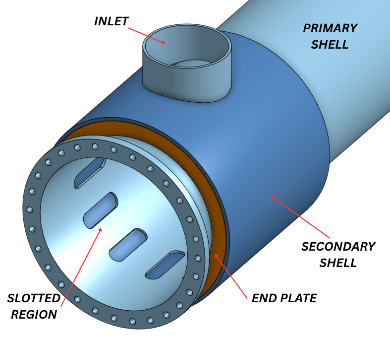
A vapour belt exchanger is a shell-and-tube ex changer that uses an additional external chamber and slotted internal shell to redistribute vapour flow around the bundle more evenly. It consists of:
- Inlet nozzle (shown on top)
- Secondary shell wrapped around the primary exchanger shell
- Secondary shell end plates
- Slots in the inner primary shell permit the desire flow distribution
Typical internal inspections of the slotted regions may note general corrosion or pitting on the primary shell with no other consideration. These locations are often thought to be for flow distribution only; an internal, not a pressure boundary component.
So, What’s the Issue?
Corrosion (and/or erosion) in the slotted region (which can occur on both sides) can result in significant thinning of the regions between the slots in the primary shell; we will call those the stay regions. The axial pressure (acting on the back of the tubesheet and head) tries to stretch the vessel axially which develops stress in both the primary and secondary shells, shown as R PS and R SS , respectively.
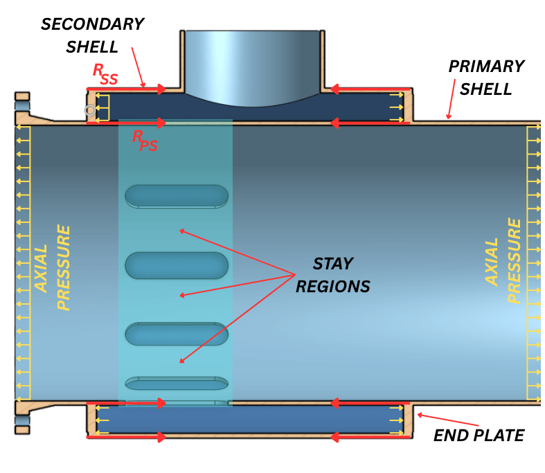
As the stay region degrades (loses thickness), load is forced into the secondary shell and end plates, changing the stress state of the exchanger. In the extreme case where the stay regions completely (or nearly) corrode to nothing, the secondary shell takes up more load AND additional bending stress is developed in the end plates. Can the stay region just corrode to nothing without any concern? – Typically, no.
ASME Design Considerations
For most vapour belt exchangers, the thickness of the primary and secondary shells is governed by circumferential (hoop) stress, with ASME Section VIII, Division 1 (S8D1) UG-27 typically controlling the required thickness for internal pressure. The real design challenge lies in the end plates.
If the vapour belt region were treated as an open space, ignoring the contribution of the primary shell and stay regions covered by the vapour belt, the end plates would typically be designed using S8D1 Mandatory Appendix 14 (MA-14) Integral Flat Heads with a Large, Single, Circular, Centrally Located Opening. This results in significant bending stresses at the junctions with the shells and would typically require end plate thicknesses several times greater than the shell thickness. In practice, this approach is rarely used because it leads to excessively thick sections and large, impractical welds.
Instead, vapour belt exchangers are typically designed using the braced and stayed surface rules of UG-47 and UG-50. In this approach the axial pressure force acting on the ends of the exchanger is resisted by the stay regions, which reduces the bending and allows for a much thinner end plate.
The design logic is relatively straightforward. The total axial force from internal pressure is:
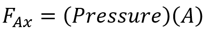
Where A is the internal cross-sectional area of the vapour belt diameter. The required load-carrying area of the stay region is then:
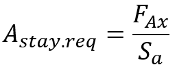
Where S a is the allowable stress of the material in tension.
A key step, and the one often overlooked, is determining the actual available stay area. This must account for the material removed for the slots and corrosion allowance from both sides. If the actual stay area exceeds the required area, the design is acceptable.
It is worth noting that this approach is inherently conservative, as it assumes the stay region carry the entire axial load. In reality, the load is shared to some extent with the primary and secondary shells. However, because this load sharing is not easily quantified manually, the stayed surface approach provides a practical and conservative design basis.
For exchangers in service, this becomes particularly important. Corrosion in the slotted region reduces the effective stay area, and in some cases, it may be necessary to:
- Recalculate the minimum required thickness of the stay ligaments
- Evaluate remaining capacity based on actual geometry of the slots (or holes)
- Perform a higher level Fitness-for-Service (FFS) analysis to better understand load sharing and reduceunnecessary conservatism.
The relationship between stay thickness and cross sectional area versus acceptability are shown below for an example exchanger.
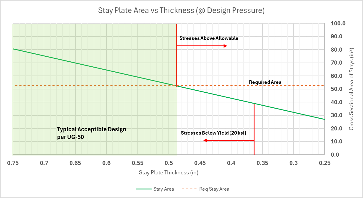
If sufficient stay area remains, the end plate thickness can continue to be justified using UG-47, resulting in a much thinner and more efficient design than would be obtained using Appendix 14.
Conclusions
The slotted region in a vapour belt exchanger is not just internal geometry, it is part of the pressure-resisting structure. The material between the slots carries load, not just flow.
When that material is reduced, the capacity of the exchanger is reduced. If that isn’t being considered, the assessment is incomplete.